Test the Murata Type 1SC radio module
This guide contains the configuration and AT commands for the Murata Type 1SC radio module (LBAD0XX1SC-DM) and evaluation board. The board is designed to provide hybrid cellular Cat-M1, narrowband IoT (NB-IoT), and satellite NB-IoT over non-terrestrial networks (NTN-IoT) data connectivity. It supports global navigation satellite systems (GNSS) and can house an integrated SIM (iSIM).
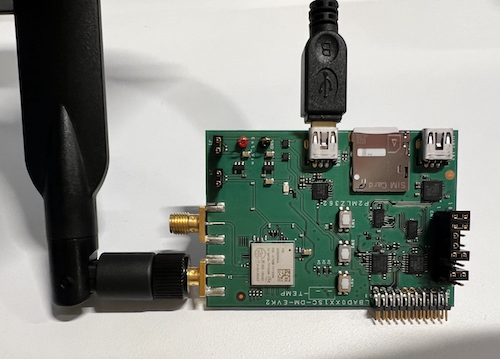
Set up the evaluation board
These instructions are for Windows users. If you have a different operating system, adjust the steps accordingly.
Attach the antenna to the board using the antenna connector. Use the image below as a reference. The antenna supports radio communications for cellular and NTN-IoT data services, as well as for GNSS.
Connect the USB cable with your PC and the UART01 port of the board. For more information, refer to the Murata Type 1SC User Guide.
In your Windows PC, go to the Control Panel and check your Device Manager for the assigned communications port (COM port) of the evaluation board (EVB).
Open PuTTY (or another SSH client), then set the connection type to Serial.
After establishing a connection between your SSH client and the module, refer to the Murata Type 1SC Application Guide to complete the initial configuration using AT commands.
AT commands for testing
To test the hybrid connectivity the Type 1SC module provides, use the following AT commands.
For more information about using AT commands to configure devices, see emnify’s Introduction to AT commands webinar.
Retrieve modem manufacturer and revision
Example response
Check version
Example response
Murata is expected to release the new Type 1SC modem firmware in the next few months.
Query ICCID and IMSI
Example response
Example response
Initial configuration
Turn on multi-RAT capability
To switch from another radio access technology (RAT) to NTN-IoT, turn on the multi-RAT capability:
Turn off automatic RAT switching
You need to turn off automatic RAT switching so you can decide when to use NTN.
Turn on auto connect mode
Restart the modem
Example response
Determine the test device location
In NTN communications, the cellular modem must know its geolocation (latitude, longitude, and altitude). The modem can be introduced to this location manually or acquired automatically by the device with its internal GNSS (iGNSS) system.
Along with the cellular modem, the evaluation kit includes a GNSS chip that can acquire its location automatically. This chip can use GPS and GLONASS systems. By default, the satellite system type is configured to GPS. At least five GPS satellites are needed to locate the device, so the device must be under open skies for the iGNSS system to work well.
During initial testing, emnify observed that communication with five satellites could only be achieved under open skies with no obstructions (for example, a ceiling) over the antenna.
This guide provides configuration options for both manual static and iGNSS. emnify recommends performing the evaluation tests using the manual static location command. You can also use iGNSS if the test device isn’t stationary and its antenna is outside with nothing covering it.
Configure the test device position manually as static and permanent
You can use the Elevation Finder to find the latitude, longitude, and altitude of the device’s location by clicking on the exact location on the map. Altitude is calculated from the earth’s surface, so, if necessary, add the extra altitude of the building where the device is located.
In the preceding example, 52.506726,13.393140 are the latitude and longitude of the emnify office in Berlin, Germany.
89 is the altitude in meters.
Be sure to update your location accordingly.
Example response
Configure the test device position automatically with iGNSS
Next, verify that iGNSS is set:
Example response
Finally, you can check how many GPS satellites are detected by the module:
At least five GPS satellites need to be detected for iGNSS to function.
Enable NBNTN RAT
Query available RAT types
Example response
Set the RAT to NBNTN
The current version of the Sony ALT1250 modem chipset doesn’t automatically handle switching between terrestrial networks ("CATM", "NBIOT") and NTN ("NBNTN").
You can switch between terrestrial and non-terrestrial networks manually with the following commands.
After changing the RAT type, the modem is unresponsive for a few seconds, and temporary settings are reset to the default values.
Set to NTN:
Example response
Set to NB-IoT (terrestrial):
Example response
Verify the RAT type currently active
Example response
Configure band
Skylo uses bands 255 and 256. Setting both frequencies is safe, but this slows down the network search and attachment time. To save time, only configure one band. Currently, 255 is used in North America and 256 in Europe. Choose the band that corresponds to your region.
Example response
Configure APN
Turn on all possible unsolicited notifications
These commands are commonly used for troubleshooting.
Turn off the radio
Turn on TA value calculation notifications
Turns on notifications about the timing advance (TA) value calculation.
Example response
Report GNSS session status changes
Turns on status events reported upon GNSS session status changes.
Example response
Send GPS fix notifications
Sends a notification when the GPS fix is successfully acquired. The modem needs to know its location to calculate the timing advance (TA) value to communicate with the satellite. This notification is received in automatic location settings.
Example response
Turn on SIB31 notifications
Turns on notifications when SIB31 is received. SIB31 is the first broadcast packet the modem receives when it’s within satellite reception.
Example response
The notification looks like the following. If you see it, you’re within radio coverage of the satellite.
Report RRC state changes
Turns on notifications about radio resource control (RRC) state changes.
Example response
Turn on network registration status notifications
Example response
Turn on the radio
Example response
Wait for automatic network registration to Skylo and emnify networks. You can verify that the device is connected successfully on the emnify Portal.
See registration status
Example response
90198 is Skylo’s network code (MCC+MNC).
There are three formats that you can use to query the network registration:
- format=0: Long alphanumeric format
- format=1: Short alphanumeric format
- format=2: Numeric format
Currently, Skylo broadcasts its network information in numeric format only as 90198.
If you don’t see any network information after the AT+COPS? command, even though CEREG proved a successful network registration, set the format to 2 (numeric format) with the following command and try again.
Example response
List available networks that the device can detect
Example response
90198 is the Skylo network code.
You’re ready to attach to an NTN network if you see it in your response.
CEREG state change report codes
The following table outlines the possible values for the reported CEREG state change.
Retrieve physical connectivity and eNB parameters information
Example response
Get signal quality (RSRP, RSRQ, SINR, RSSI)
Example response
While these signal levels seem like there’s no connection for terrestrial networks, they’re normal levels in NTN. Anything below -120 is considered as no signal for NTN.
Generate IP data traffic by PING over ICMP
Example response
Generate IP data traffic over UDP
Allocate UDP socket
Skylo doesn’t support TCP, so IP data usage is over UDP. This command creates an IPv4 UDP socket. The modem’s response establishes the socket ID so it can be used to send or receive IP data over UDP.
You should include the information about your application server in this command.
Replace 192.0.2.0 with the IP address of your application server and PORT with the UDP port.
If you don’t have an application server with UDP, you can use the free server from Datacake.
Example response
Activate the predefined UDP socket
Use the socket ID from the response of the preceding socket allocation command.
Example response
Check the UDP socket status
Example response
Send UDP packet to a remote server
Replace SOCKET_ID with the integer response from the preceding command, DATA_LEN with the length of the data you’re sending in bytes, and DATA with the data you’re sending encoded as hex digits.
The following example command sends “text message” to the remote server.
Example response
If your application server sends back a response, you see the following notification:
To read the received data, you can use the following command:
Example response
Deactivate the UDP socket
Example response
Delete the UDP socket
Example response
Datacake
If you don’t have an application server to send data to, you can use an online service like Datacake. You can try Datacake’s free package with a few devices.
You can send data from your NTN-IoT device to the Datacake server (upload direction). However, it’s not possible to send data from the Datacake server to the device (download direction).
The application server address is https://app.datacake.de/
Create a free account. The NTN device must be defined as a Dragino NB-IoT type device. Refer to the Datacake documentation for further instructions.
Important highlights
IMEI is the device-ID with an f added to the beginning of a 15-digit IMEI, making the device-ID a 16-digit number.
When you use Datacake as the application server, the server address and the UDP port that you should use in the allocation command is:
- Server:
67.207.76.90 - Port:
4445
The final command looks like this:
The first eight bytes of the payload data must match the device-ID you configured on Datacake. For the rest of the payload, the platform allows you to define some decoders of your own if needed.
Power Saving Mode (PSM)
Enable PSM
Turn on Power Saving Mode (PSM) and assign the requested values for Requested_Periodic_TAU and Requested_Active_Time.
You can also use your own values.
Example response
Subscribe to URCs
Subscribe to unsolicited result codes (URCs) to include PSM parameters of Active Time and periodic TAU as the last two parameters of the CEREG report.
Verify assignment to the UE
You can also manually check whether the Active Time and the extended periodic TAU have been assigned to the LTE device (UE).
Example response
Extended Discontinuous Reception (eDRX)
Verify eDRX parameters
Retrieve the extended Discontinuous Reception (eDRX) parameters to check if any parameters have been configured already.
Example response
Configure eDRX parameters
Typically, you configure eDRX parameters of Requested_eDRX_cycle and Requested_paging_time_window in a single command.
The command is formatted as follows:
Replace mode, AcT-type, and Requested_eDRX_value with the values you want to set.
For example:
Example response
The following table outlines the possible mode values:
The following table outlines the possible AcT-type values:
The Requested_eDRX_value is 0101 to 81.92 seconds.
In the Sony modem, this command only takes the Requested_eDRX_cycle, as shown in the following example:
In this case, an example response would follow this format:
Example response
Retrieve eDRX parameters
Example response
In the preceding example, you request a value for the eDRX cycle, and the network (NW) replies with an NW-provided eDRX value. Additionally, you also receive an NW-provided paging time window.
If you need to request a specific paging time window value, use a separate command.
For example, 5 corresponds to 15.36 seconds for the Requested_paging_time_window:
Example response
Example response
In this example, the network provided a paging time window of 1 to 5.12 seconds.