Test the Quectel CC660D-LS radio module
Test the Quectel CC660D-LS radio module
The Quectel CC660D-LS is a 3GPP non-terrestrial network (NTN) satellite communication module. This guide contains the configuration and AT commands for the module and evaluation board.
Set up the evaluation board
These instructions are for Windows users. If you have a different operating system, adjust the steps accordingly.
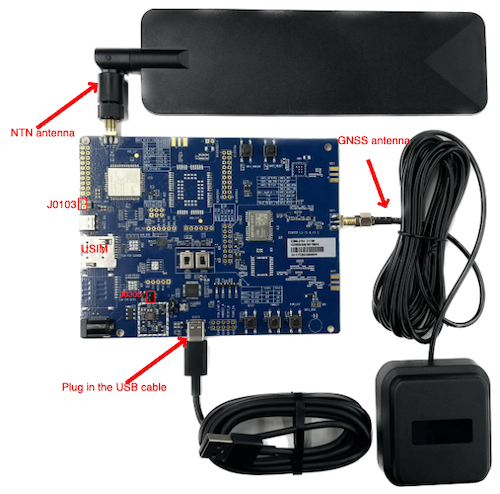
Attach the antennae (NTN and GNSS) to the board to the board using the antenna connectors. Use the image below as a reference.
Connect the USB cable to your PC and the board’s UART port. Make sure you’ve installed the USB-to-UART driver on your PC.
Set the jumpers to ensure the correct voltage as described in the Quectel CC660D-LS TE-B User Guide.
In your Windows PC, go to the Control Panel and check your Device Manager for the assigned communications port (COM port) of the evaluation board (EVB).
Open PuTTY (or another SSH client), then set the connection type to Serial.
After establishing a connection between your SSH client and the module, refer to the Quectel AT Command Guide to complete the initial configuration.
Available AT commands for testing
To test the satellite connectivity the CC660D-LS module provides, use the following AT commands.
CC660D-LS only supports NTN (that is, NBNTN), so there’s no radio access technology (RAT) selection available.
For more information about using AT commands to configure devices, see emnify’s Introduction to AT commands webinar.
Retrieve modem manufacturer and revision
Example response
Query IMEI
Example response
Query ICCID
Example response
Query IMSI
Example response
Set and query APN
Set the Access Point Name (APN) to em:
Example response
Query the current APN:
Example response
Configure band
See available bands:
Example response
Get the currently active bands:
Example response
Skylo uses bands 255 and 256. Setting both frequencies is safe, but this slows down the network search and attachment time.
Example response
To save time, only configure one band. Currently, 255 is used in North America and 256 in Europe. Choose the band that corresponds to your region.
Example response
Request GNSS information
Replace STATUS with an integer that indicates whether the embedded microcontroller unit (MCU) needs to provide GNSS information.
The following example command indicates that the MCU needs to provide GNSS information:
Example response
Set GNSS information
The MCU uses this command to actively set and query the terminal’s current GNSS position information. The module uses the inputted GNSS position information for satellite communication timing and frequency compensation.
Example response
When the module needs GNSS position information, it actively reports the unsolicited result code (URC) +QGNSSINFO: 1 to notify the MCU to input GNSS position information to the module.
Replace the placeholders according to your GNSS information using the following table as a reference.
The following example command sets the GNSS information to the emnify office on the nineteenth floor in Berlin, Germany:
Example response
Turn on registration status notifications
Example response
Query available networks
Example response
90198 is the Skylo network code.
You’re ready to attach to an NTN network if you see it in your response.
Query registration status
Example response - Not registered to any networks
Example response - Registered to Skylo
Register on a specific network
Typically, the module attaches to the Skylo network quicker automatically (that is, AT+COPS=0).
But for debugging, you can use the preceding command to manually attach to the Skylo network.
As a result, you should see a reported CEREG state change.
The following table outlines the possible values.
Check network status
This command is used in engineering mode.
There are four available modes to pass to this command:
Example response
The response contains the following values:
Generate IP data traffic by PING over ICMP
Example response
Generate IP data traffic over UDP
Skylo NTN doesn’t support Transmission Control Protocol (TCP) connections.
Create UDP socket
Creates an IPv4 UDP/IPv4 socket. The modem’s response establishes the socket ID so it can be used to send or receive IP data over UDP.
Example response
Establish UDP connection with a remove server
Replace SOCKET_ID with the integer response from the preceding +ESOC command, REMOTE_PORT with the remote listener port, and REMOTE_ADDRESS with the IPv4 address of the remote server.
Example response
Send UDP packet to a remote server
Replace SOCKET_ID with the integer response from the preceding +ESOC command, DATA_LEN with the length of the data you’re sending in bytes, and DATA with the data you’re sending encoded as hex digits.
The following example command sends “text message” to the remote server. The response in ASCII read: “9999test message0000”
Example response
Close socket
Replace SOCKET_ID with the integer response from the preceding +ESOC command.
The following example command closes the socket with ID 1:
Example response